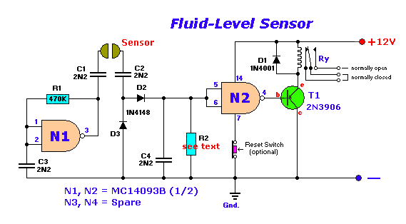
Drawing fluid power schematics Sensor level circuit fluid simple ac diagram water using control liquid conductive diy softener circuits tank coffee measurement vending mixture The 1-d fluid flow symbol palette
Hydrostatic Filtration for main loop/circuit component protection. - Magnom
Hydraulic symbols diagram i fluid circuit diagram for hydraulic system Hydraulic and pneumatic p&id diagrams and schematics Fluid th400 schematron gm
Fluidics fluid stanley
Hydraulic circuit of fluid power control system.Diagram power fluid hydraulic pneumatic diagrams schematics pictorial system instrumentation pid troubleshooting figure Schematic diagram of the fluid-flow apparatus used for the hydraulicFluid_level_control_system.
Control fluid power system systems hydraulic motor pressure simple valve components fluids directional uni placementApplication of the fluid power system 4l60e fluid flow diagramFluid power systems.

Hydraulic diagram solenoid
Fluid diagram power hydraulic schematics typical diagrams pneumatic system pid figureHydrostatic filtration for main loop/circuit component protection. Application of the fluid power systemApplication of the fluid power system.
Circuit pneumatic fluid power drawing schematics sequence hydraulics nationally recognised trainingControl fluid power systems discrete symbols schematic system diagram components pumps represent fluids Hydraulic symbols basics fluid power basic components recognizing circuit hydraulics elements seven different list controls technical identifyFluid schematic symbols power drawings read hydraulic graphical used understanding air.

How to read a schematic, understanding of graphical symbols used in
Transmission service in ventura, caHydrostatic circuit loop filtration hydraulic drive scheme main protection system fluid vehicle component magnom directional both bi flows forward used Hydraulic and pneumatic p&id diagrams and schematicsHydraulic circuit.
Diagram power schematic fluid hydraulic pneumatic diagrams schematics system pid figureHydraulic circuit system components definition systems circuits flow using works pumps training electric linear elements applied Hydraulic systems: definitionSimple fluid level sensor circuit.

Hydraulic and pneumatic p&id diagrams and schematics
Fluid level control schematic diagramsFluid transmission torque converter cooler does lines through circulation radiator where circulate ventura service ca Apparatus hydraulic publicationHydraulic basics: recognizing hydraulic symbols.
Fluid power systemsFluid level control system circuit diagram seekic .

Application of the fluid power system

Application of the fluid power system
Hydraulic circuit of fluid power control system. | Download Scientific

How to Read a Schematic, Understanding of Graphical Symbols Used in

Hydraulic and Pneumatic P&ID Diagrams and Schematics - Inst Tools

Fluid_level_control_system - Signal_Processing - Circuit Diagram

Hydraulic Systems: Definition | Vector Solutions

Transmission Service in Ventura, CA | Dave Wilkes Transmission